

Views: 0 Author: Site Editor Publish Time: 2026-06-23 Origin: Site
Uneven sheet cutting represents a severe operational bottleneck. It functions as a compounding cost issue rather than a mere visual defect. When cuts warp or display inconsistent kerf tapers, you immediately face high scrap rates. Downstream assembly failures multiply rapidly. These defects ultimately destroy your production margins. Uneven cutting rarely stems from a single isolated variable. It typically arises from a complex interplay between operator parameters and material behavior under thermal stress. The underlying condition of your sheet cutting machine dictates much of this baseline quality. We will provide an evidence-based diagnostic framework to troubleshoot these existing cutting issues. You will discover how to evaluate modern equipment capabilities. We will outline how specialized upgrades structurally prevent these edge defects. Our goal is to equip you with practical strategies for stabilizing your daily yields.
Thermal and Mechanical Variables: Uneven cuts are primarily driven by unmanaged heat-affected zones (HAZ), misaligned optics/mechanics, and unreleased internal material stresses.
Design for Manufacturing (DFM): Part geometry—such as large empty cutouts—can compromise structural rigidity during processing, leading to unpredictable warping.
Equipment Upgrades Dictate Tolerances: Overcoming persistent uneven cutting often requires migrating from legacy systems to advanced setups (e.g., automated focal adjustment, specialized roll-to-sheet tracking).
Vendor Selection is Critical: Partnering with a reliable precision cutting machine manufacturer ensures access to the strict machine calibration and responsive technical support for cutting machines necessary to maintain baseline flatness and edge quality.
Poor flatness disrupts subsequent manufacturing steps entirely. Uneven edges often manifest as a 5 to 10 degree kerf taper. This taper creates nightmare scenarios for automated bending operations. Press brakes rely on consistent material dimensions to calculate bend angles accurately. When edge geometry varies, robotic systems fail to seat the material properly. Precision welding also requires flush, uniform joints. Irregular gaps force welders to overcompensate with filler metal. This slows down the entire line. Final assembly grinds to a halt. Workers must manually force warped parts into alignment. They waste valuable time correcting upstream mistakes.
Edge quality serves as the primary driver of machine profitability. Uneven cuts consistently result in wasted raw material. This reality hurts deeply when processing high-value metals like stainless steel or aerospace-grade aluminum. Operators throw away expensive blanks simply because the edges failed inspection. Furthermore, uneven cuts demand increased manual deburring. Workers spend countless hours grinding away dross and smoothing jagged profiles. These hidden labor hours destroy your equipment return on investment. You lose money on material. You lose money on labor. Machine uptime drops while operators struggle with rework.
Operators often attempt to force a worn machine to hit tight tolerances, which creates a dangerous operational fallacy. You cannot cheat physics. Pushing miscalibrated drives beyond their physical limits accelerates mechanical wear-and-tear. Servomotors overheat when fighting extreme friction. Belts stretch further under artificial strain. This establishes an urgent need for proper root-cause diagnostics. Temporary workarounds only mask the underlying decay. You must address the actual mechanical faults. Fixing the true source of the problem restores sustainable precision. Ignoring it guarantees a catastrophic breakdown.
Inconsistent focal points disperse cutting energy unevenly across the sheet. Focus determines how concentrated the thermal energy becomes at the material surface. When the focal distance fluctuates, the kerf width widens unpredictably. This causes severe local flatness variations. Kerf angles become inconsistent from one end of the cut to the other. Dirty lenses also disrupt the beam profile. Spatter and vaporized metal coat the optics over time. This contamination absorbs energy instead of focusing it. The edge quality suffers immediately when the beam loses its optimal geometry.
We must examine the physics of the heat-affected zone (HAZ). Heat input often exceeds a material's inherent capacity to dissipate it. Thinner gauges struggle significantly with thermal buildup. Stainless steel retains heat much longer than mild steel. Localized thermal expansion forces the sheet to bow mid-cut. The material curls upward toward the cutting head. This thermal distortion ruins dimensional accuracy. It also introduces the risk of severe mechanical collisions. If the nozzle strikes a warped sheet, it can destroy the entire cutting head.
Mechanical backlash throws the cutting head off its programmed path. Worn drive belts introduce hesitation during direction changes. Unlevel cutting beds alter the physical distance between the nozzle and the material surface. These alignment issues create jagged or wavy edges. The machine controller might execute perfect code. However, the physical gantry cannot translate those commands accurately. Loose pinion gears cause micro-stutters during high-speed curves. You will notice distinct serrations along the cut edge. These mechanical deviations render high-tolerance geometries impossible to achieve.
Inadequate clearing of molten material exacerbates edge roughness. The assist gas serves two purposes. It shields the cut and physically blows molten slag through the kerf. When gas pressure drops, heat pools inside the cut zone. This trapped heat melts the surrounding material excessively. The cut edge becomes rough and severely oxidized. Underside dross accumulates rapidly when the gas fails to eject the liquid metal. Operators must chisel this hardened dross away manually. Consistent gas flow remains non-negotiable for a clean, even edge.
Visible Defect on Cut Part | Primary Mechanical Root Cause | Secondary Parameter Issue | Recommended Action Step |
|---|---|---|---|
Wavy or serrated edge profile | Mechanical backlash in gantry | Excessive cutting speed for material | Inspect pinion gears and belt tension |
Inconsistent kerf taper angles | Degraded or dirty focal lens | Incorrect focal distance offset | Clean optics and recalibrate auto-focus |
Severe underside dross buildup | Low assist gas pressure | Incorrect nozzle standoff height | Check gas supply lines for leaks |
Sudden material bowing | Unlevel cutting bed support | Overheating in concentrated zones | Re-level slats and optimize cut path |
Sheet materials carry significant residual internal stresses. Rolled steel absorbs tension during the cold-rolling process. Extruded plastics inherit similar molecular strains. The continuous sheet traps these physical forces inside its core. The cutting action releases this stress abruptly. When you slice through the tension lines, the material physically springs back. This can manifest as sudden, violent warping. The sheet will distort even if your machine parameters are absolutely perfect. You cannot fix internal material stress with a software setting. You must account for it during the initial planning phase.
Specific part designs heavily influence cut quality. Large skeletal cutouts reduce the physical rigidity of the sheet mid-process. Reduced mass means less material remains available for heat dissipation. The machine pumps thermal energy into a diminishing physical footprint. This drastically increases the risk of thermal deformation. Slender webs and delicate bridges warp almost instantly under the beam. As the machine removes more material, the remaining skeleton loses its structural integrity. The sheet practically melts into itself. This design flaw destroys complex geometrical nests entirely.
High-reflective materials behave very differently than standard mild steel. Aluminum and brass reflect thermal energy back toward the optics. They require distinct power modulation to pierce cleanly. Standard mild steel absorbs energy much more predictably. Using "one size fits all" parameter settings guarantees uneven yields. Operators often apply steel settings to galvanized sheets. The zinc coating vaporizes unpredictably, causing severe edge pitting. You must establish strict, material-specific parameter libraries.
Distribute thermal loads: Program the cutting path to jump between different quadrants. This prevents localized heat buildup in one corner.
Reinforce delicate structures: Use micro-joints to keep fragile internal geometries tethered to the main skeleton.
Design self-supporting grids: Avoid grouping multiple large cutouts next to each other. Leave enough web material to dissipate heat.
Orient parts logically: Align long, narrow parts parallel to the rolling direction of the raw material grain to minimize tension release.
Modern equipment uses advanced capacitive height sensing. This technology maintains a continuous, perfect focal distance dynamically. The sensor measures the gap between the nozzle and the sheet in real-time. It adjusts the Z-axis instantly if it detects topographical variations. Slight ripples in the material no longer ruin the cut. The focal point remains locked onto the surface. This structural adaptation prevents the machine from crashing into warped sections. Adaptive cutting guarantees a uniform kerf width across the entire production run.
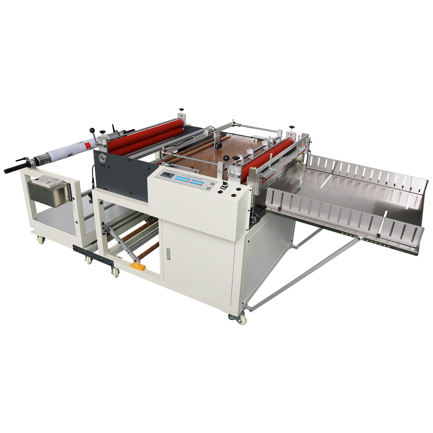
Non-rigid or continuous web materials require sophisticated handling. You cannot simply pull continuous rolls across a static bed. They require advanced registration and dynamic tensioning. We highly recommend utilizing an Eye Position Roll To Sheet Cutting Machine for these applications. This specialized equipment utilizes precise optical tracking. It scans printed eye marks on the web to guarantee exact cut placement. It automatically adjusts for microscopic material shifting. This prevents progressive material skewing over long production runs. Precision indexing eliminates the cumulative dimension errors found in legacy friction-feed systems.
Modern CAM software utilizes powerful features to control thermal dynamics. Path optimization distributes heat evenly across the entire sheet. The software employs skip cutting to jump between distant parts. This prevents one specific zone from turning into a thermal sink. Lead-in and lead-out points minimize thermal shock on the actual part boundary. Engineers use micro-joints to hold prone-to-warping parts rigidly in the skeleton. Small tabs of uncut metal secure the piece firmly. The parts remain locked flat against the bed until the cycle finishes entirely. Operators simply snap them out afterward.
Buyers must rigorously scrutinize machine architecture. You should look for structural elements that absorb kinetic energy. Cast iron beds provide superior vibration dampening. Heavy-duty extruded gantries resist twisting during high-speed acceleration. Mass equals stability in the cutting world. This inherent structural rigidity ensures the machine resists operational vibration. It maintains critical mechanical calibration over years of heavy shift work. A lightweight frame will flex under rapid movements. This flexing translates directly into wavy cut edges. You cannot out-program a flimsy machine base.
Initial setup dictates long-term equipment performance. A credible vendor validates bed leveling meticulously upon delivery. They ensure perfect laser or plasma beam alignment across the entire cutting envelope. Technicians must verify gantry squareness using precision alignment tools before final handover. Poor commissioning guarantees uneven cutting from day one. If the machine starts its life misaligned, every part it produces will carry that defect. You must demand a comprehensive factory acceptance test onsite.
After-sales service functions as your primary risk mitigation strategy. Predictable production requires exceptional, ongoing backing. You must partner with a highly reliable precision cutting machine manufacturer. They supply the engineering depth required to solve obscure cutting anomalies. Furthermore, your facility requires fast, accessible technical support for cutting machines. This support must include remote diagnostic capabilities. Technicians should log into your machine to check drive faults remotely. The vendor must provide rapid parameter library updates for new materials. Accessible maintenance training empowers your local operators to prevent failures autonomously.
Solving uneven sheet cutting demands a strictly holistic approach. You cannot rely on parameter tweaks alone to fix structural problems. You must optimize your part design using DFM principles. You need to dial in exact thermal and mechanical parameters for specific materials. Most importantly, you must operate highly rigid, well-calibrated equipment.
Consider these actionable next steps to stabilize your yields:
Run standardized test cuts on your specific material grades to baseline current performance.
Perform detailed time studies to measure your current manual rework hours caused by poor edges.
Conduct strict tolerance checks on parts from different corners of the cutting bed to identify gantry wear.
We encourage you to consult with an engineering specialist today. Audit your current scrap rates thoroughly. Explore machinery upgrades capable of stabilizing your production line permanently.
A: A natural kerf taper of 5 to 10 degrees is expected in certain processes. However, unevenness usually indicates a specific mechanical fault. The focal point might be set incorrectly for your specific material thickness. A misaligned beam path can also strike the nozzle edge, distorting the cut. Additionally, dirty optics alter the beam geometry, scattering energy unevenly. Check your focal length and clean your lenses immediately.
A: You must reduce the overall heat input. Optimize your cutting speeds to move the thermal source faster. Utilize skip-cutting paths in your CAM software to distribute heat evenly across the entire sheet. Employ micro-joints to secure fragile parts securely within the main skeleton during the cut. This prevents localized thermal expansion from lifting the material off the bed.
A: Yes, it affects quality significantly. A damaged, uneven honeycomb or slat bed causes the material to sit unlevel. This physically forces the cutting head out of its optimal focal range. The sensor struggles to compensate for drastic dips in the bed structure. Consequently, you will experience inconsistent edge quality, poor piercing, and severe underside dross.
A: You should expect robust remote diagnostic capabilities. Technicians must check drive logs and parameter faults digitally. Vendors should offer rapid parts dispatch for common wear items like lenses and nozzles. Furthermore, expect dedicated application engineering support. They should help you dial in exact parameters when you introduce new, difficult materials to your production line.
